ECE 486 Control Systems
Lecture 3
Impulse Response
Recall from last time, we introduced state-space model, a modern approach with which we can describe control systems with a unified framework.
\begin{align*} \dot{x} &= Ax + Bu \\ y &= Cx, \end{align*}where
- \(x(t) \in \RR^n\) is the state (vector) at time \(t\);
- \(u(t) \in \RR^m\) is the input (vector) at time \(t\);
- \(y(t) \in \RR^p\) is the output (vector) at time \(t\);
- \(A \in \RR^{n \times n}\) is the dynamics matrix;
- \(B \in \RR^{n \times m}\) is the control matrix;
- \(C \in \RR^{p \times n}\) is the sensor matrix.
A natural question arises
Question: Given a dynamical system, how do we determine the output \(y\) for a given input \(u\)?
Note: We will only consider single-input, single-output (SISO) systems, i.e., \(u(t),y(t) \in \RR\) for all times \(t\) of interest. In the above notation for state-space model, \(m=p=1\) means the system is SISO.
Definition of Impulse Response
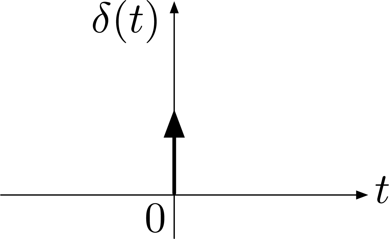
Recall from ECE 210, a unit impulse or Dirac’s $δ$-function is a function of time which satisfies,
- \(\delta(t) = 0\) for all \(t \neq 0\) and
- \(\displaystyle \int^a_{-a}\delta(t) \d t = 1\) for all \(a > 0\).

Figure 1: Unit impulse or Dirac’s $δ$-function
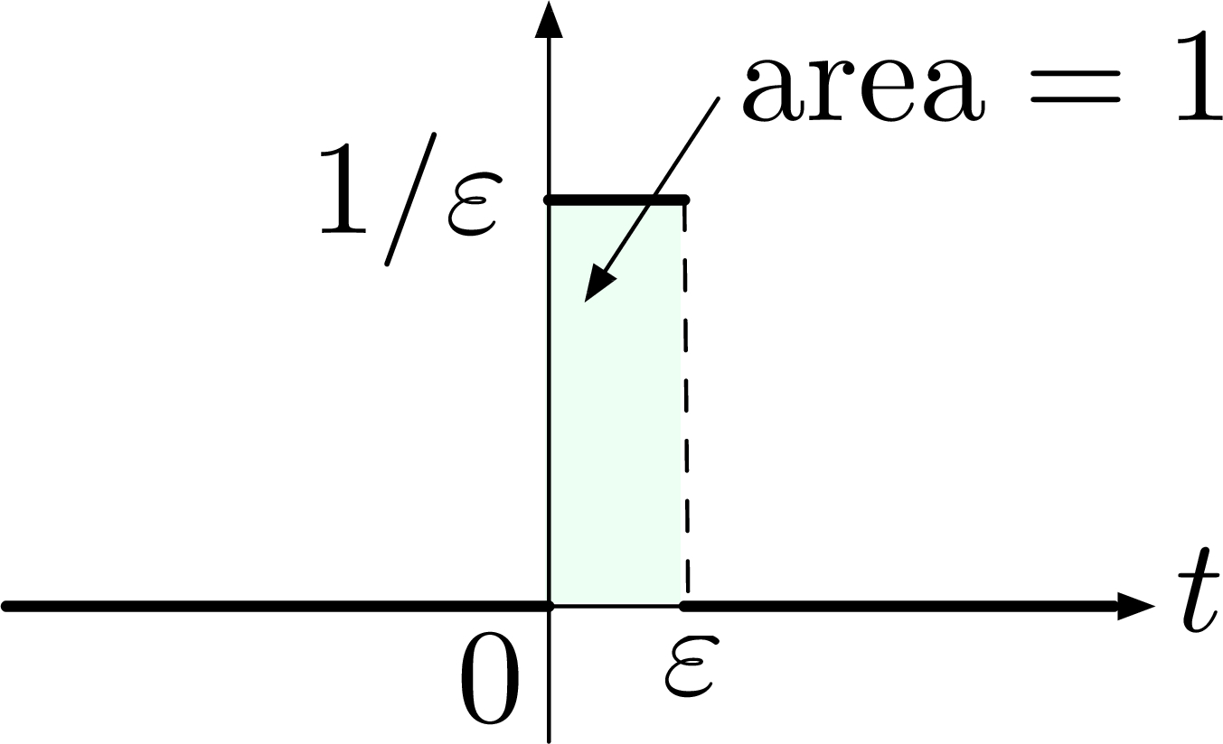
We can think of \(\delta(t)\) as a limit of impulses of unit area as shown in Figure 2. As \(\varepsilon \to 0\), the impulse gets taller \(\frac{1}{\varepsilon} \to + \infty\), but the area under its graph remains at \(1\).

Figure 2: Step signal with width \(\varepsilon\), height \(\frac{1}{\varepsilon}\)
System Output as Convolution Integral
Now consider the input \(u(t) = \delta(t-\tau)\) (unit impulse applied at time \(t=\tau\)), given a linear and time-invariant (LTI) system with zero initial conditions (IC) as in Figure 3, the system output \(y(t) = h(t-\tau)\). This function \(h\) is called the impulse response of the system.

Figure 3: Linear system with zero initial conditions \(x(0) = 0\).
Given system impulse response \(h\), we can find the system’s response to other (arbitrary) inputs. Indeed, recall the sifting property of the $δ$-function: for any function \(f\) which is “well-behaved” at \(t=\tau\), we have
\begin{align} \label{d3_eq1} \int^\infty_{-\infty} f(t)\delta(t-\tau)\d t = f(\tau). \end{align}Equation \eqref{d3_eq1} says the $δ$-function “sifts out” the value of \(f\) at \(t = \tau\). Therefore, any reasonably regular function can be represented as an integral of impulses.
To compute the system’s response to other (arbitrary) inputs by a given \(h\), we can write this input signal \(u\) in integral form by the above sifting property,
\begin{align*} u(t) = \int^\infty_{-\infty}u(\tau)\delta(t-\tau)\d\tau. \end{align*}By superposition principle, the response of a linear system to a sum (or integral) of inputs is the sum (or integral) of the individual responses to these inputs, i.e.,
\begin{align*} u(t) &= \int^\infty_{-\infty} u(\tau)\delta(t-\tau) \d\tau \quad \longrightarrow \\ y(t) &= \int^\infty_{-\infty}u(\tau)\underbrace{h(t-\tau)}_{\text{response to} \atop \text{$\delta(t-\tau)$}}\d\tau. \tag{2} \label{d3_eq2} \end{align*}The integral in Equation \eqref{d3_eq2} that defines \(y(t)\) is a convolution of \(u\) and \(h\).
Superposition Principle: For all linear systems, the net response caused by two or more stimuli is the sum of the responses that would have been caused by each stimulus individually.
Thus, for an LTI system with zero initial conditions, its output is the convolution of the input with the system impulse response,
\begin{align*} y(t) &= u(t) \star h(t) \\ &= h(t) \star u(t) \\ &\triangleq \int^\infty_{-\infty} u(\tau) h(t-\tau)\d\tau. \end{align*}Unfortunately, the formula in the definition does not provide a convenient way of computing the output \(y\) for a given input \(u\). A more practical is to use Laplace Transform.
Laplace Transforms and the Transfer Function
Transfer Function
Recall the two-sided Laplace transform of a function \(f(t)\) is the integral transform
\begin{align*} \tag{Laplace} \label{d3_lt} F(s) = \int^\infty_{-\infty} f(\tau)e^{-s\tau}\d\tau, \end{align*}where \(s \in \CC\) is a complex variable.
We can use the table below to establish the quick correspondence between time domain and frequency domain signals.
| time domain | frequency domain |
| \(u(t)\) | \(U(s)\) |
| \(h(t)\) | \(H(s)\) |
| \(y(t)\) | \(Y(s)\) |
And convolution in time domain \(y(t) = h(t) \star u(t)\) is equivalent to multiplication in frequency domain \(Y(s) = H(s)U(s)\) through Laplace transform.
\begin{align*} Y(s) &\triangleq \LL \{y(t)\} \\ &= \LL \{h(t) \star u(t) \} \\ &= \LL \{h(t)\} \LL \{u(t)\} \hspace{2cm} \text{(by the above equivalence btwn. time and frequency domain)}\\ &\triangleq H(s) U(s). \end{align*}In particular, the Laplace transform of the impulse response \[H(s) = \int^\infty_{-\infty}h(\tau)e^{-s\tau}\d\tau\] is called transfer function of the system.
When we consider causal systems, whose output at time \(t\) is not affected by inputs at future times \(t' > t\), we agree that \(h(t) = 0\) for \(t < 0\), where \(h(t)\) is the response at time \(t\) to a unit impulse at time \(0\).
We will take all other possible inputs (not just impulses) to be \(0\) for \(t < 0\), and work with one-sided Laplace transforms
\begin{align*} y(t) &= \int^\infty_{\color{red}{0}} u(\tau)h(t-\tau) \d\tau, \\ H(s) &= \int^\infty_{\color{red}{0}} h(\tau)e^{-s\tau}\d\tau. \end{align*}Computing Transfer Functions
Here we want to answer another question—Given \(u(t)\), we can find its
transform \(U(s)\) by using tables of Laplace transforms or MATLAB, but how
about \(h(t)\) or \(H(s)\)? Recall the LTI system in Figure 3, in this
specific case, we can use the following formulae,
More on these formulae will be discussed much later this semester.
But at the moment let’s look at a quick example with a single input and a single output.
Example 1: Consider the system dynamics
\begin{align*} \dot{y}(t) &= -ay(t) + u(t), &\qquad \text{(think $y(t)=x(t)$, full measurement)} \\ u(t) &= e^{st}. &\qquad \text{(always assume $u(t) = 0$ for $t < 0$)} \end{align*}Compute system transfer function \(H(s)\).
Solution: Given \(u(t) = e^{st}, t \ge 0\), we think of \(s\) as some fixed number. Then
\begin{align*} y(t) &= \int^\infty_0 h(\tau)u(t-\tau)\d\tau \qquad \text{(by $u \star h = h \star u$)}\\ &= \int^\infty_0 h(\tau)e^{s(t-\tau)}\d\tau \\ &= e^{st} \int^\infty_0 h(\tau)e^{-s\tau}\d\tau \\ &= e^{st}H(s). \end{align*}Substitute
\begin{align*} \dot{y}(t) &= \frac{\d}{\d t}\left(H(s)e^{st}\right) = sH(s)e^{st} \end{align*}into the governing differential equation \(\dot{y}(t) = -ay(t) + u(t)\),
\begin{align*}\require{cancel} sH(s)\cancel{e^{st}} &= -a H(s)\cancel{e^{st}} + \cancel{e^{st}}, \qquad \forall~ s, t > 0 \\ sH(s) &= -a H(s) + 1 \tag{3} \label{d3_eq3}. \end{align*}Solve for \(H(s)\) in Equation \eqref{d3_eq3}, we have
\begin{align*} H(s) &= \frac{1}{s+a}, \tag{4} \label{d3_eq4}\\ \implies y(t) &= \frac{e^{st}}{s+a}. \end{align*}If we look up the right hand side of the transfer function in Equation \eqref{d3_eq4} from tables, then the impulse response \(h(t)\) by taking the inverse Laplace transform is
\begin{align*} h(t) &= \begin{cases} e^{-at}, & t \ge 0 \\ 0, & t < 0 \end{cases} \end{align*}This example can be illustrated using the chart,

Figure 4: Linear system with zero initial conditions \(x(0) = 0\).
Frequency Response
We already know how to find \(y\) for a given \(u\) with a known \(h\). But given an input \(u(t) = e^{st}\), do we follow Example 1 and repeat for all \(s\) of interest in order to compute the ratio \[ H(s) = \frac{y(t)}{u(t)}? \]
That is to say, compute \(H(s) = \dfrac{y(t)}{u(t)}\), repeat for as many values of \(s\) as necessary according to Figure 5.

Figure 5: Compute the transfer function = compute the ratio \(H(s) = \frac{y(t)}{u(t)}\)?
One problem of this approach is that \(e^{st}\) either blows up very quickly if \(s > 0\), or it decays to \(0\) very quickly if \(s < 0\).
Instead, our input signals shall be sustained, bounded signals. That’s why when we introduced Laplace transform in Equation \eqref{d3_lt}, \(s\) is allowed to be a complex number \(s \in \CC\).
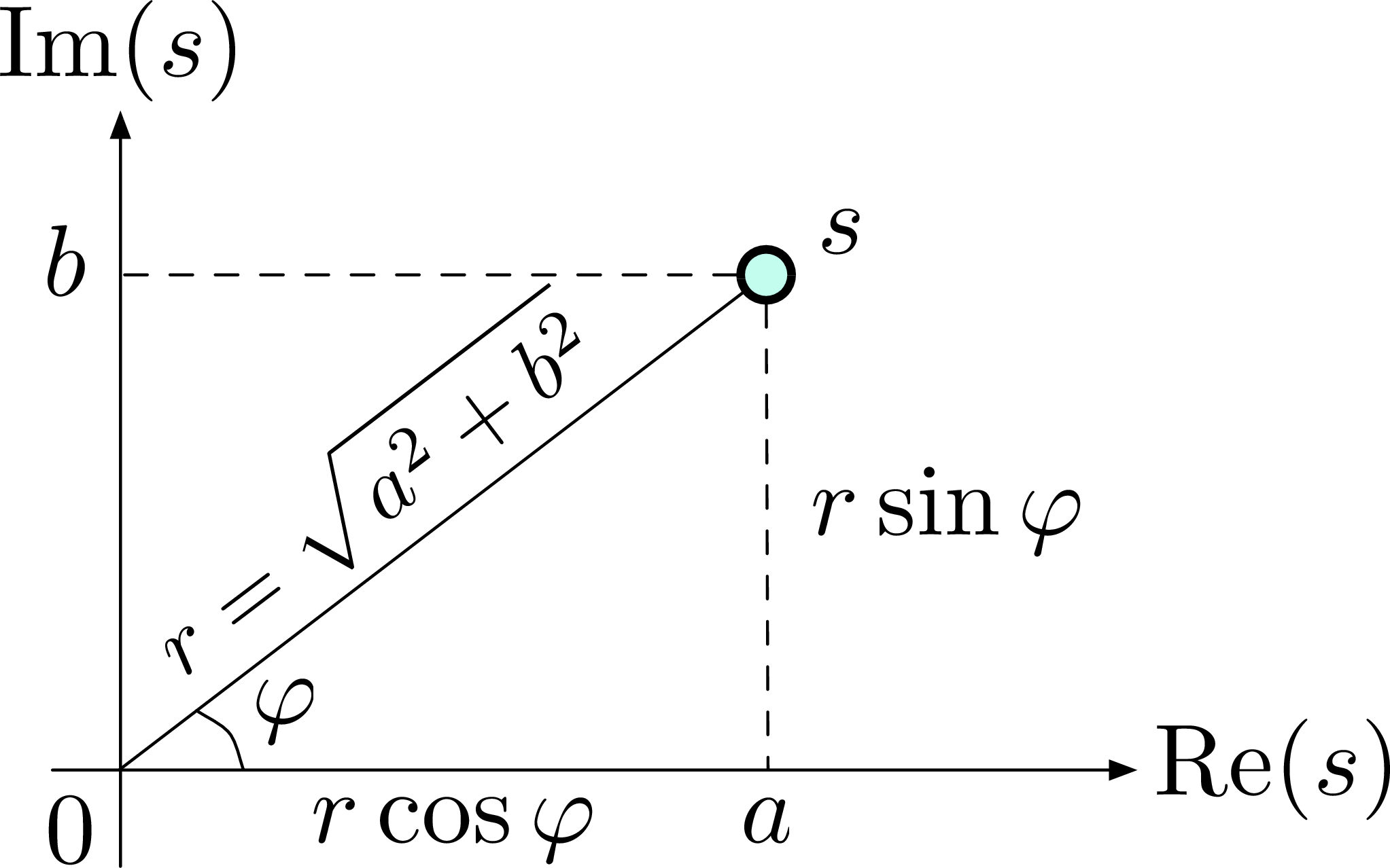
Basics of Complex Numbers: We can visualize a complex number \(s = a+jb \in \CC\) with an Argand diagram,
\begin{align*} s &= \underbrace{a}_{\text{real} \atop \text{part}} + j\underbrace{b}_{\text{imaginary} \atop \text{part}}. \qquad \text{(geometric representation in $\CC$)} \end{align*}
We can also use its polar form,
\begin{align*} s &= re^{j\varphi}, \\ r &= |s| = \sqrt{a^2 + b^2}, &\qquad\text{(magnitude or modulus)} \\ \varphi &= \angle s = \tan^{-1}\left(\frac{b}{a}\right).&\qquad\text{(phase or argument)} \end{align*}Euler’s formula: \(e^{j\varphi} = \cos \varphi + j \sin \varphi\).
Do you know? Euler’s identity, which is a special case of the formula, relates the five most important mathematical numbers, i.e., \(0\), \(1\), \(e\), \(i\) or \(j\), and \(\pi\) by Euler’s equation \(e^{i \pi} + 1 = 0\).
Consider the LTI system with zero initial conditions, given a sinusoidal input \(u(t) = A\cos(\omega t)\) with amplitude \(A\), frequency \(\omega\) in rad/s, we can compute the system output \(y(t)\).

Recall the complex cosine function in \(z \in \CC\) is defined as \[ \cos (z) \triangleq \frac{e^{iz} + e^{-iz}}2. \]
It also makes sense based on Euler’s formula above. Therefore, by linearity, the response \(y(t)\) is \[ y(t) = \frac{A}{2} \Big( H(j\omega)e^{j\omega t} + H(-j\omega)e^{-j\omega t}\Big), \] where
\begin{align*} H(j\omega) &= \int^\infty_0 h(\tau)e^{-j\omega\tau}\d\tau, \\ H(-j\omega) &= \int^\infty_0 \underbrace{h(\tau)e^{j\omega\tau}}_{\text{complex}\atop\text{conjugate}}\d\tau \\ &= \overline{H(j\omega)}. \end{align*}Note that \(h(\tau) \in \RR\) is a real valued function and \(H(j\omega) \in \CC\). Denote
\begin{align*} H(j\omega) &= M(\omega)e^{j\varphi(\omega)} \\ H(-j\omega) &= M(\omega)e^{-j\varphi(\omega)}, \end{align*}since both are complex numbers thus having magnitudes and phases.
If we rewrite \(y(t)\),
\begin{align*} y(t) &= \frac{A}{2} M(\omega)\Big( e^{j(\omega t + \varphi(\omega))} + e^{-j(\omega t + \varphi(\omega))}\Big) \\ &= A M(\omega) \cos\big(\omega t + \varphi(\omega) \big) \hspace{3cm} \text{(steady state)} \\ \tag{5} \label{d3_eq5} &= A\underbrace{M(\omega)}_{\text{amplitude}\atop\text{magnification}} \cos\big(\omega t + \underbrace{\varphi(\omega)}_{\text{phase}\atop\text{shift}}\big). \end{align*}Equation \eqref{d3_eq5} says the (steady-state) system response to a cosine signal with amplitude \(A\) and frequency \(\omega\) is still a cosine signal but with amplitude scaled \(AM(\omega)\); same frequency \(\omega\), but with phase shift \(\varphi(\omega)\).
We shall learn in the next lecture that system response to general signals (not necessarily sinusoidal signals) is always given by \(Y(s) = H(s)U(s)\). For system with nonzero initial conditions, the system response is described by
\begin{align*} \text{total response} = {\text{transient response} \atop \text{ (depends on I.C.)}} + {\text{steady-state response} \atop \text{ (independent of I.C.)}} \end{align*}if the system is stable.