Project
| # | Title | Team Members | TA | Documents | Sponsor |
|---|---|---|---|---|---|
| 4 | Motorized Imaging System for Plant Root Research Honorable Mention |
Jimmy He Nachiket Joshi Nathaniel Keri |
Kyle Michal | appendix1.zip design_document3.pdf final_paper1.pdf presentation1.pdf proposal1.pdf |
|
| This proposal covers a motorized imaging system that takes photos of a tall plant's root by transporting a camera down a standard, transparent observation tube into the soil, taking multiple pictures from the ground up, and outputting a panoramic image of the entire root, which is used for scientific research in the field of agriculture. The imager device is comprised of a base station on the ground resembling a hoist, and a suspended camera placed into the observation tube, which itself has motors that centers it laterally in the tube so it always takes images facing up. A central control server serves to control, manage and collect images from a fleet of imagers, and also to present a GUI to the user with live progress and diagnostics data from each imager. ## Background This project is done in collaboration with the College of ACES and SoyFACE Farm (The collaboration has been confirmed.) The SoyFACE Farm contains a corn research facility, where an observation tube is installed by each of the over 1000 corn plants, that goes 5ft deep. Each week, researchers would collect a panoramic image of the roots of each plant to access its health condition. The imaging process is implemented with a bulky camera mounted on a 5ft-long rigid stick. The operator mounts the base of the stick on the observation tube on a fixed mounting point, and inserts the stick deep into the tube. The camera is connected to an equally bulky control box consisting of a laptop, a large car battery and control circuitry of the camera crammed inside of a Pelican case. The camera depth can be read from a ruler on the stick, which the operator needs to input to the laptop, and invoke the "Start" command. The laptop will then verbally instruct the operator to pull the camera up centimeter-by-centimeter at a set interval (usually 1 second), taking a picture at each instruction until the camera is completely out. Any non-compliance of the verbal instruction will ruin the image and require a restart. The set of images are then taken to an external program to be stitched into a panoramic image. The same time-consuming and strength-demanding exercise is carried out over each of the 1000+ corn each week, and the research group demands for an automated solution. ## Overview of Improvements The solution calls for building a system that is able to traverse down the tube, taking all the required images and stitching the images without human intervention except for mounting it on observation tubes. Furthermore, the system should be inexpensive and scalable such that multiple imaging appliances can operate at the same time in different tubes, while centrally managed by an operator. This also requires the solution to be cost-effective, small and easy to mass-produce. ## Components The larger system can be split into two components, a Management Platform (MP) and an Imaging Appliance (IA). The IA can be further split into the Camera Assembly and the Base Station. The following discussion about the components is centered around the block diagram. 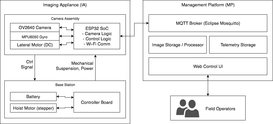 The main logic of IA runs on top of an ESP32 SoC inside the camera assembly. It accepts control signal from the operator from the MP, through a MQTT connection over its built-in Wi-Fi. It also has a serial (RS-485) link to the control board in the Base Station, in order to receive battery condition data and transmit signals to control the hoist motor, which in turn manipulates the physical depth of the camera in the tube. The Camera Assembly also has a alignment stepper motor with wheels, that centers the camera view in the tube as the camera could have shifted during the up/down motion. This shift is sensed from the built-in gyroscope and corrected by stepping the alignment motor. The ESP32 SoC is connected to a OV2640 camera, that captures a 2 mega-pixel image at every run. It is fixed-focus since the distance from the camera to the plant root is known. When imaging, the camera first travels up by a fixed distance (\~2cm) such that the view overlaps with the previous, and takes a image. It then compresses the image into JPEG and transmits it to the MP. The base station of the IA is placed above ground, preferably mounted on top of the observation tube. It contains a battery to power the entire IA, and a stepper motor that hoists the camera assembly into the tube. The camera assembly sends control signal in terms of distance to move, and the ATmega328 MCU in the ground station translates it into angular motion before commanding the stepper motor. It also has an endstop switch to indicate the home (Z=0) point. The MCU is also connected to a battery charging / monitoring IC that can charge the battery and report battery level to the camera assembly, such that it can home itself and refuse imaging when the battery level drops low. The Management Platform (MP) runs on a physical machine of any platform (such as an x86 Linux server) and optionally also act as the Wi-Fi AP for each IA to connect to. The heart of the MP is an MQTT broker collecting telemetry and images from and emitting control signals to one or more IA's. Upon reception of images, it processes the image set and stores a panoramic image into its image storage. Upon reception of telemetry, it stores the telemetry in a volatile database for tracking. It exposes a Web UI to the frontend users, such that the users can view and download the images, as well as monitor and control the IA's. When used, the operator enters the name of the image (matching the current date and ID of the observation tube) and presses "Start", starting the automatic imaging sequence of the selected IA. The operator then monitors the Z depth of the camera in real time as an indicator of the imaging process. When done, the operator may download the panoramic image already stitched from the camera. ## Originality and Use of External Solutions We propose that all mechanical parts of the base station, the casing of the camera and the motion mechanisms will be custom designed. The circuit boards of the entire imager will be custom made and assembled. There are no known solution to the problem of taking and no other alternative to the original camera-on-stick approach, according to the researchers. Of course, considering the complexity of the circuitry and the infeasibility of integration in the lab environment (soldering of a CMOS sensor, etc), the supporting circuitry of the camera and the accelerometer will be purchased as a module. The controlling software requires several open-source projects used as libraries to provide APIs to established protocols, including Eclipse Mosquito for MQTT broker, Paho-MQTT for the MQTT Client implementation, and Flask for the HTTP framework. The main controlling logic and camera-handling code running on top of a ESP32 SoC uses Espressif's ESP-IDF SDK/HAL suite, and if necessary, the motor and battery manager board uses the Arduino SDK for its convenient stepper implementation. The interface of OV2640 to ESP32 is known and a library will be used whenever appropriate. ## Criterion for Success The overall effectiveness of the project can be assessed in three aspects: Functionality, Repeatability and Effectiveness. Functionality can be measured by having an imager device take a panoramic picture from a real plant, and checking the following. First, a valid panorama should be returned, and each image comprising the panorama must not be yawed more than +/-15 degrees from each other to certify the lateral motion compensation. Second, the central management system should report real-time progress from the imager at all times. Repeatability can be measured by comparing two consecutive images taken from the same plant, and there should not be significant differences in the geometry of the images and features. Effectiveness can be measured by having the entire imager cost less than $200, without a complex manufacturing procedure that consumes more than 2 man-hours in assembly. Success of the project can be certified if the above criteria are met. |
|||||